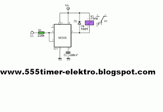
In this circuit the 555 timer is used in a novel way, as a voltage controlled switch.The old and omnipresent NE555 can be very good at something it was not meant for: driving relays or other loads up to 200 mA. The picture shows an example circuit: if the input level rises over 2/3 of the supply voltage – it will turn on the relay, and the relay will stay on until the level at the input drops below one third of the supply voltage.
If the relay and D1 were connected between pin 3 and ground, the relay would be activated when the input voltage drops below one third, and deactivated when the input voltage goes over two thirds of the supply voltage. It is also a nice advantage that the input requires only about 1 uA, which is something bipolar transistors can’t compete with. (This high impedance input must not be left open.) A large hysteresis makes the circuit immune to noise. The output (pin 3) can only be either high or low (voltage-wise), and it changes its state almost instantenously, regardless of the input signal shape.
The voltage drop across the NE555’s output stage (at 35-100 mA) is 0.3-2.0 V, depending on the way the relay is connected and the exact current it draws. D1 is absolutely vital to the safety of the integrated circuit.
No comments:
Post a Comment